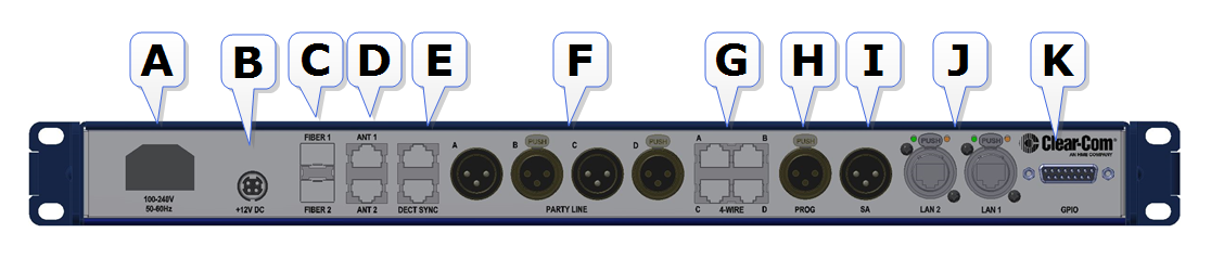
FreeSpeak II Base rear connectors
 Click to enlarge image
| A | Power connector. Mains power lead with internal current converter. |
| B | Power connector. DC wallwart power lead (Part # 453G032, 12V DC, 60W). Use connector A or connector B or both to guard against power failure. |
| C | Fiber connector to FS II splitter (Part # FSII-SPL). Used with Fiber module (Part # HCI-SMFO or MMFO) |
| D | RJ45 connector to antenna ( FSII-TCVR-19, FSII-TCVR-24) or splitter. |
| E | Dect Sync. RJ45 connector to another Base Station. Can also be used to synchronise to other Clear-Com DECT devices. In some cases you will need a cross-over cable instead of a standard cable. See Pinouts |
| F |
XLR Partyline connectors (standard microphone cable). Note: If power is enabled on these ports the power operates across a pair of ports, A & B, C & D. See Power 2-wire beltpacks from the Partyline. See Pinouts Be sure to null the ports whenever cabling arrangements are changed. |
| G | RJ45 connectors for 4-wire intercom. These ports can change pin polarity according to whether they are connecting to a matrix or another device. See Port Function . |
| H | XLR connector (standard microphone cable) for Program Feed input, typically from a mixing console or audio player. Adjust levels in Audio Settings/Program Input in the Base Station menus. |
| I | XLR connector (standard microphone cable) for Stage Announce output. |
| J | 2 x RJ45 ports. These can be used for network connection or for daisy-chaining devices. Note: The ports share an IP address, so only one network connection is possible (either port can be used). |
| K | GPIO connector. See Pinouts . |
Note: For connection between the Base and antenna/splitter and digital audio feeds, Clear-Com recommends shielded Cat 5/6 cable. Use of other cable can result in shorter cable runs and other performance problems.