Crosspoint Map
Use the Crosspoint map to give a visual display of all crosspoints or source-to-destination assignments in the matrix system. The crosspoint map is a graphical representation of all inputs and outputs in the system.
You can use this map to identify talk and listen assignments, forced listens and blocked listens. You can also use it to make or cancel crosspoints and to override input and output levels set up in the map.
The grey triangles denote active crosspoints, pink half circles denote auto listen crosspoints, red crosses denote blocked listen crosspoints and violet half circles denote forced listen crosspoints.
The crosspoint map displays both the labels and the port numbers the labels are associated with for ease of identification.
-
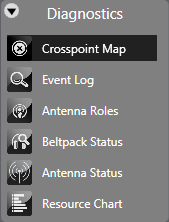
Select Diagnostics > Crosspoint Map
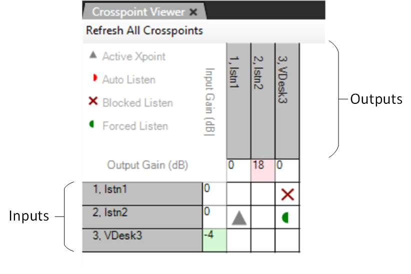
The inputs are listed down the left-hand side of the table with the input gain settings, while the outputs are listed along the top of the table with the output gain settings.
-
Right-click a cell representing a crosspoint to display a list of options. To toggle a crosspoint from the On state to the Off state click on the State option and then click on Toggle in the next menu. Select the Kill option from the State menu to clear a crosspoint completely.

-
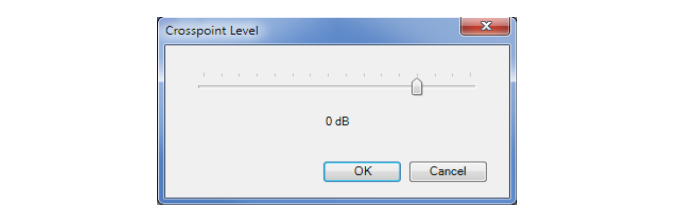
To set the crosspoint level, select the level option on the menu to display the crosspoint level slider and set the required level.
Note: Leave signalization still active on the panel.
-
Select the Refresh All option to update the display with the crosspoint settings current on the matrix.
-
Use Ctrl+ (zoom in) and Ctrl- (zoom out) to zoom in or out, producing clearer views of the map, or if a wheel mouse is available use Ctrl and the wheel to zoom.
-
Click on the Refresh All Crosspoints button at the top of the crosspoint map to request the crosspoint information from the matrix and use it to update the crosspoint map.
When an input or output level is changed it affects all the crosspoints that are connected to the port. If an input level for a port is reduced the input level to all the crosspoints for that port is reduced (all the crosspoints in the column below the level). If an output level is changed all the crosspoints in that row are affected. Note that these levels only change the input and output levels for the ports. They do not change the crosspoint level settings.
-
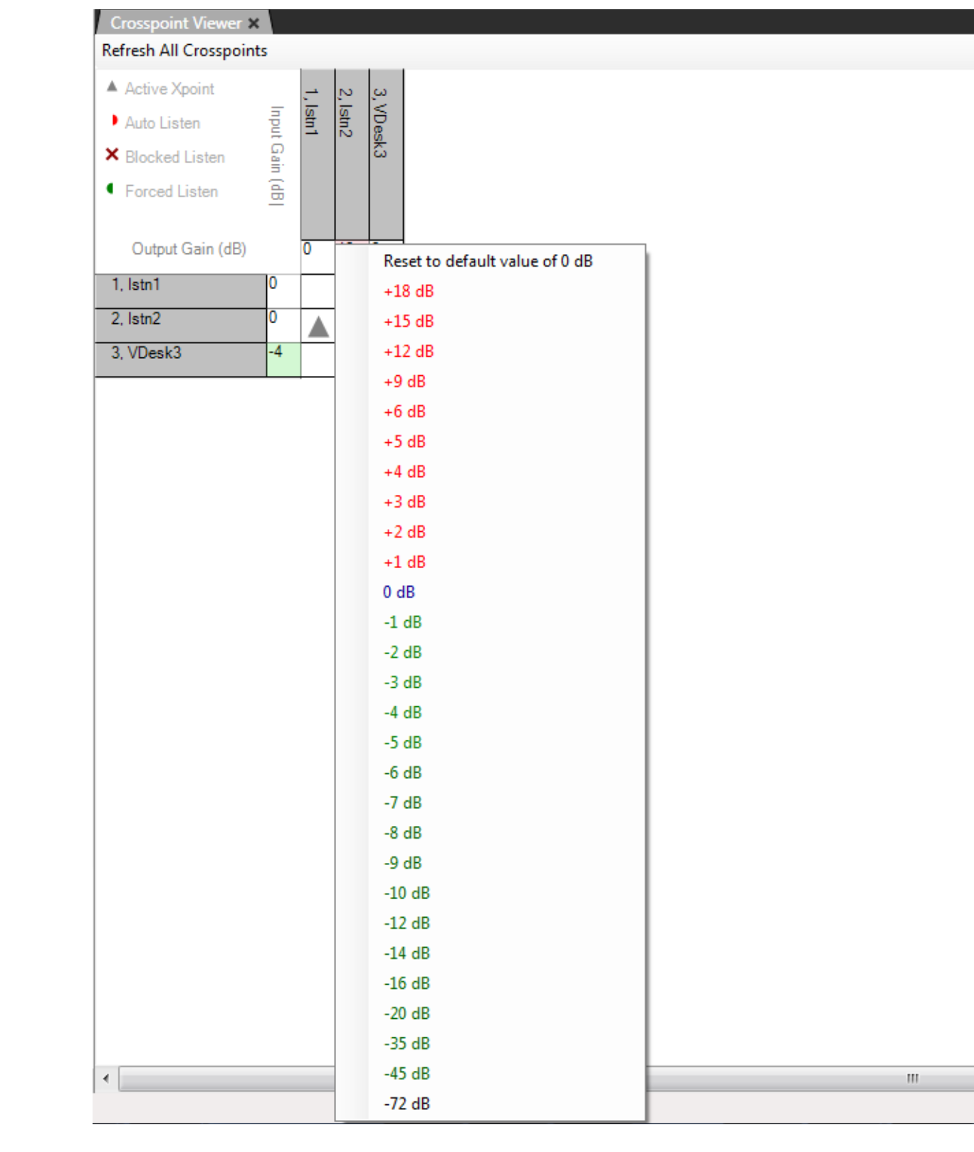
Right-click on an input or output setting (the cell next to the port information) to display a list of gain values.
Clicking a value in the list sets the input or output gain to the required level in the matrix. This value remains in force until it is either changed again using the Crosspoint Monitor, or a new map is applied, and the matrix is reset to the default values in the map.
If the matrix is only reset without a new map applied the modified values set up using the Crosspoint Monitor remain in force.
The settable values are: +18, +15, 12, +9, +6, + 5, +4, +3, +2, +1, 0, -1, -2, -3, -4, -5, -6, -7, -8, -9, -10, -12, -14, -16, -20, -35, -45 and -72dB.
The current value can also be reset to the default value set up in EHX from this list.
The input/output cells are color coded to show whether the level is higher (red) or lower (green) than 0dB.
You can set the default port gain using the individual port settings on the Cards & Ports screen. The setting is applied to the matrix as part of the map and is displayed by the crosspoint monitor.
-
Right-click the port gain setting to display the gain levels and show this value as the default setting, so the port may be reset to the EHX value at any time without applying a new map and a reset.
If the port gain is set to a non-zero level in EHX and then set to zero using the crosspoint monitor the gain is shown highlighted in light blue to indicate that the zero value is not the default value in the map.